0 x item(s)
KMRC Skrifa - 3rd and 4th Rail Electrification Systems - Part 2 - Modelling Guide
Our Guildford Branch team member and Network Rail Signalling designer, Simon Paley, takes a look at the 3rd and 4th Rail electrification systems. In his Part 1 Skrifa post here he described the background and design, in this Part 2 post he provides a step by step guide how to install 3rd and 4th rail on your layouts. In his final part 3 in the series he discusses the conductor rail accessories and other relevant lineside details.
Conductor Rail Installation
Once you have, using the information in the Part 1 Skrifa post here, decided where your third rail is going to be fitted, you can start fitting it.
PECO has provided a video instruction guide here:
However, when installing third rail on my new exhibition layout, I have found a slightly easier installation method:
1. Remove the Peco IL-120 Conductor rail insulators from the sprue, I don’t bother with the washers provided as they are too fiddly for my liking. I also don’t bother painting the insulators as there are generally white porcelain anyway (although there are newer grey plastic ones as well).
2. Having measured (by eye mostly) the rail lengths I need, I cut the rails where necessary using a slitting disc such as a GM693 Gaugemaster Model Railway Value Drill Set, but a pair of XU2175 Xuron Track Cutters will work just as well.
I bend in a ramp and then join the rails together using PECO Z Gauge Code 60 Rail Joiners.
3. Using a 0.8mm drill bit in a pin vice sch as the GM577 Gaugemaster Pro Archimedean Drill Set, I drill the holes for the insulators as per the dimensions and diagrams in Part 1.
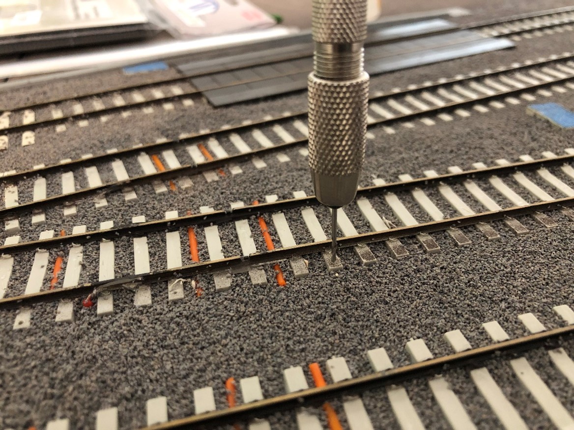
4. I then thread the insulators onto the rail by holding the insulators on a work surface and poking the rail end on through the insulator.
5. I then space the insulators out roughly before trail fitting them into the pre-drilled holes.
6. I remove the conductor rail, being carefully not to move the insulators too much then apply glue to the holes before pushing the insulators back into holes. I use AD-55 Deluxe Materials Glue and Glaze as it gives a quick strong bond and dries clear.
7. Once the glue has tried, I hand paint the rails using a rust coloured paint. Whilst the rust colour may not be fully prototypical, I want the third rail to stand out slightly.
As my layout is to be taken to exhibitions, I have to ensure that the conductor rail is not damaged when splitting the baseboards. For this I put a PECO Brass Track Pin at the baseboard edges and solder the conductor rail to it.
Further Reading
Although not 3rd or 4th Rail related check out Simon's book Colour Light Signalling for Model Railways.
ISBN: 9781785006258 Published in October 2019.
Keep in Touch
We also publish regular project updates on our "Latest News" section here and also in our Weekly newsletter, if you are not already signed up for the newsletter you can do so here.
What do you think? Get in touch with your thoughts, suggestions for future post or suggestions for future models!
-

Academy Models
-

Accurascale
-
AFV Club
-

AIP by Bachmann
-
Airfix
-

Arnold
-

ATD Models
-

Auhagen
-

Bachmann
-

Bachmann Narrow Gauge
-

Bachmann USA
-
Barrie Stevenson
-

Bassett-Lowke
-

Berko
-

Busch
-

Cambrian
-

Clark Railworks
-

Corgi
-

Cornerstone
-

Dapol
-

DCC Concepts
-

Deluxe Materials
-

Dundas
-

Easy Model
-

Eckon
-

EFE Rail
-

EFE Road
-

Emhar
-

ESU
-

Exclusive First Editions
-

Faller
-

Fleischmann
-
Gaugemaster
-

Gecko Models
-

Golden Valley Hobbies
-

Graham Farish
-

Greenlight Collectibles
-

Heljan
-

HK Models
-

Hornby
-

Hornby International
-

Hornby TT:120
-

Humbrol
-

I Love Kit
-

Jouef
-

K&S Metals
-

Kadee
-

Kato
-
Kernow Models
-
Kestrel
-

Kibri
-

Lenz Digital
-
LightCraft
-

Liliput
-

Lionheart Trains
-

Merit
-

Metcalfe
-

Middleton Press
-

Mirror Models
-
Miscellaneous
-

model scene
-

ModelMaker
-

Murphy Models
-

Noch
-

Oxford Diecast
-

Oxford Rail
-

Parkside by Peco
-

PECO
-

Plastruct
-

Platform 5
-

PM Model
-

Preiser
-

Proses
-
RailMatch
-
Rapido
-

Ratio
-

Revell
-

Revolution Trains
-

Rivarossi
-

Roco
-
Roden
-

Scale Model Scenery
-

Scalextric
-
Shawplan
-

Slaters
-
Smiths
-

Springside
-
Star Tec
-
Strathwood
-

Superquick
-

Takom
-
Taliesin
-

Tillig
-
Tiny Signs
-

Toyway
-
Tracksetta
-

Train-Tech
-

TrainSave
-

Trumpeter
-

Viessmann
-

Vollmer
-

Wills
-

Woodland Scenics
-

Xuron

Connect with us socially

